Portable datalogger
POWERING A RASPBERRY-PI WITH A SOLAR CELL
Oct 2020 - Feb 2021

Project links
-
https://picspipe.herokuapp.com/recent/15
-
Mongo DB
-
https://github.com/Paulami/picspipe
-
Heroku
Materials
-
-
-
https://www.amazon.com/AKZYTUE-2800mAh-Battery-Rechargeable-Connector/dp/B07TVDPV6W/
-
https://www.adafruit.com/product/1525
-
https://www.adafruit.com/product/2465
-
https://www.adafruit.com/product/390?
-
Contributors
THE CHALLENGE
Designing a portable visual data logger to track environment changes
This project was inspired by my interest in off-grid living and open data, especially different forms in which data is collected. So I wanted to build a visual data logger that captures the time-lapse of the environment when the sun is at its brightest and sends it to a server.
CHALLENGES
1. Powering the Pi using appropriate solar cell
Powering a Pi for a small scale project is challenging for a couple of reasons. Unlike an Arduino or Pi zero, it needs an Amereage of 2.5A to boot.
2. Finding the right object storage service
I was searching for an OSS that will storage text and images for free. It took a lot of of back and forth to finally arrive at the service I ended up using, Heroku. As I figured out later, it would have best to store all the images on AWS S3.
3. Limited funds
This project was self-funded so I was dependent on materials easily available at Micro Center and ITP floor.
THE OUTCOME
A simple Heroku-based app that shows images over a period of time.
The image below is derived from the testing phase and shows a time-lapse over a day.

STEP 1
PLANNING THE TYPE OF SOLAR CELL MODULE
Working with a solar cell is a different challenge compared to running a project on a regular battery or regulated power supply. A lot depends on what it needs to be powered, how it will operate, where will it be placed etc.
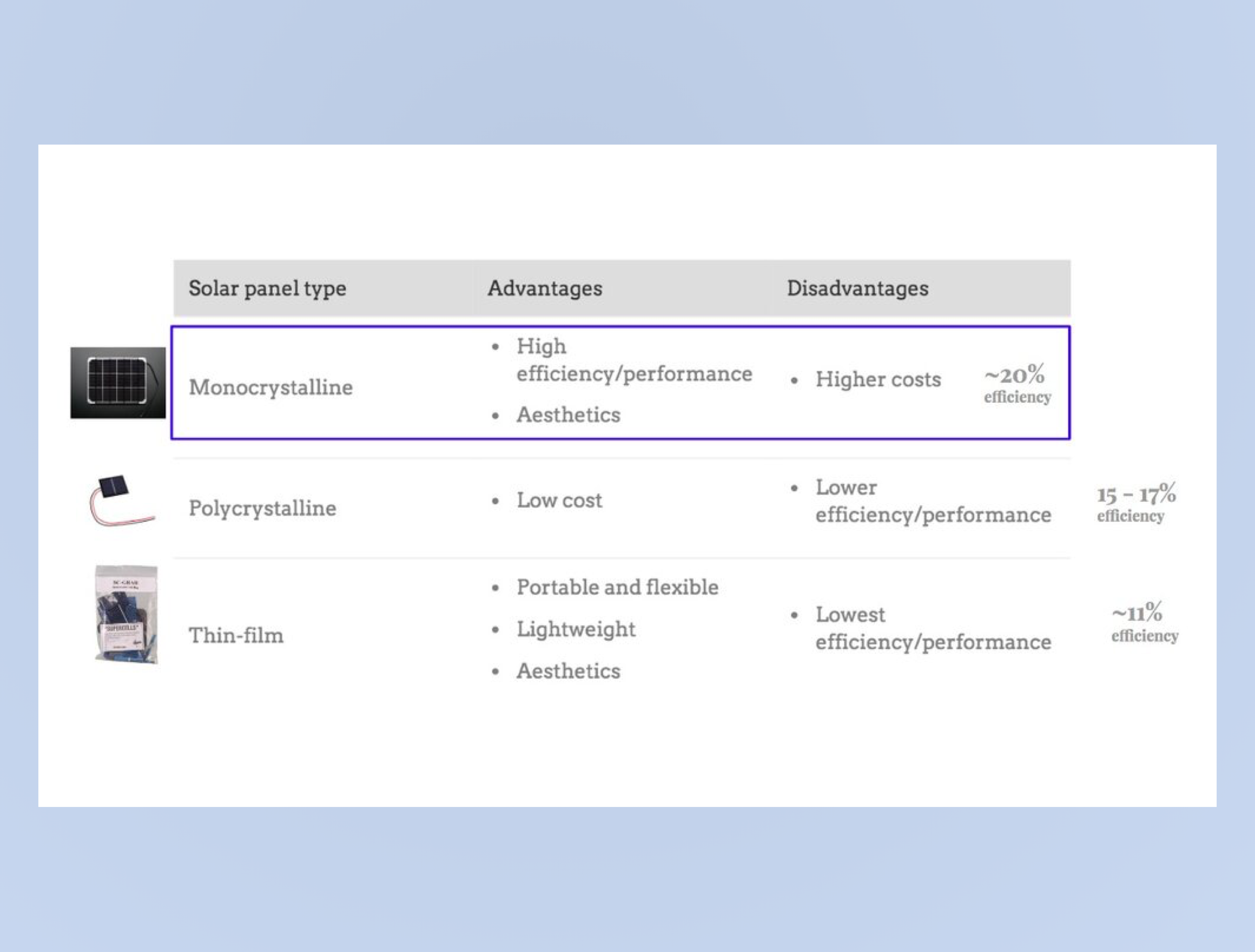
TYPES OF CELLS
As you see in the image on the left, I started with the thin-film cells. These are industrial-grade scraps that I bought on Jameco. These are 0.5 V and the current depends on the size. As the description of the product says, these are extremely thin and soldering them is a painful process. They are so brittle that I realized very quickly that I will not be able to undo any mistakes without breaking them.

https://stickmanphysics.com/
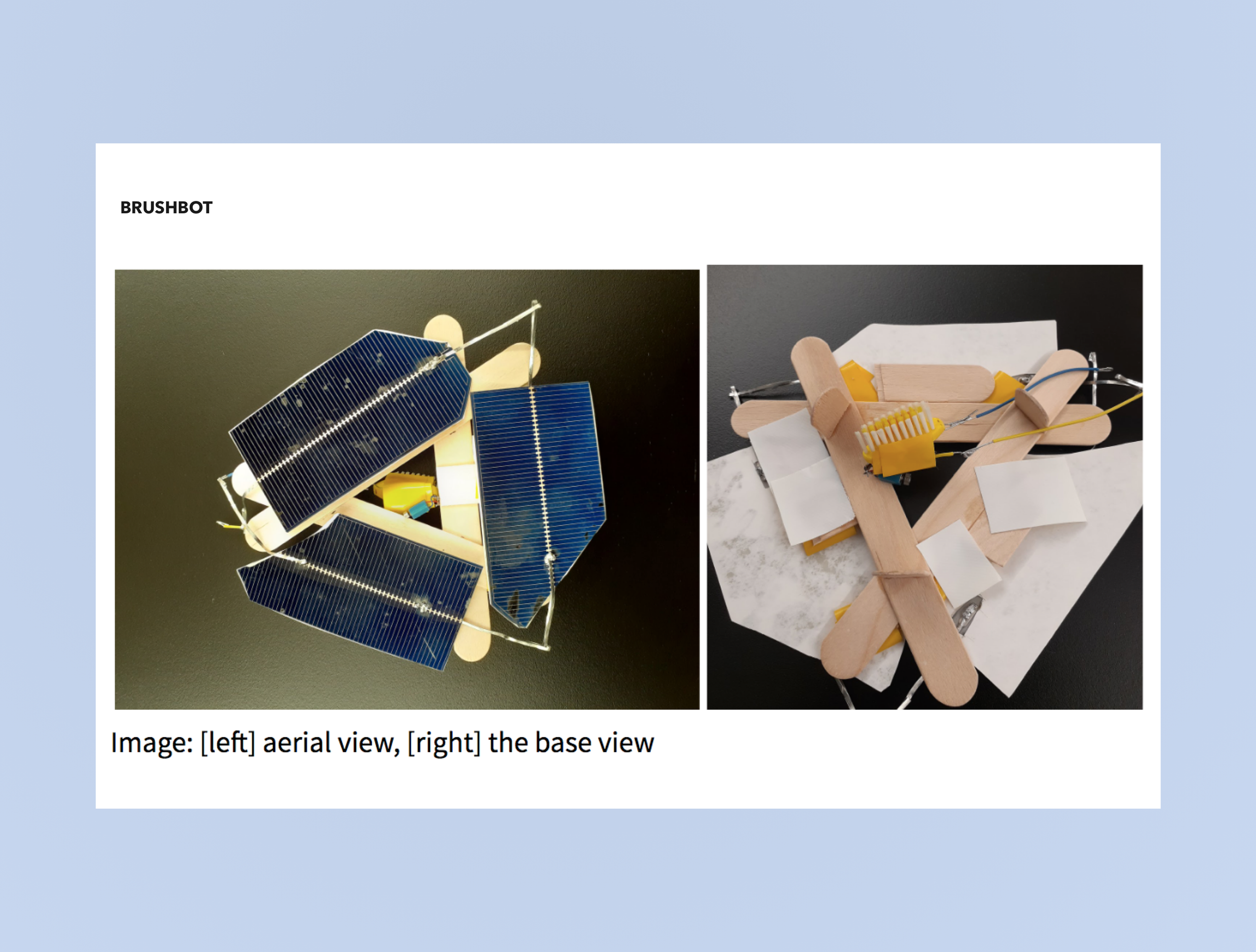
2. EXPERIMENTING WITH DIFFERENT CELLS
In the (left-bottom) image, I tried making a brush bot using the scrap cells. I was surprised at how different the process was versus using a coin cell 3V Lithium battery. The current depends on the size of the cells and when soldered in parallel, the current can significantly reduce if a cell breaks. I ended up using three cells and the entire bot was too heavy to move as a result. I tested it out under the solar workbench.

[3] Solar bench at ITP, NYU
3. EFFICIENCY
One other challenge is the efficiency of a solar cell. The Jameco thin cell had an efficiency of ~11%. So I switched to the polycrystalline pre-soldered cell like the one here. These come pre-soldered and have an efficiency of 15-17%. I tested the project mostly under the solar workbench and realized that the weather (Fall in New York is cloudy) isn’t the best for a solar project. So I switched to the Monocrystalline cell for its efficiency and ability to operate in sub-optimal lights.
STEP 2
BUILDING A TIMELAPSE WITH PI
I planned on using the Raspberry Pi for two reasons:
[4] Power consumption for Pi3
Functionality: Unlike the Arduino, the Raspberry Pi can do a lot more computing. In this project, I ended up doing all the computing at the server level.
Material availability: I needed a camera that is lightweight and available. I found the Raspi v2.1 cam which only works with Pi 3 + boards. Since I started the project in Fall, buying materials was dificliut due to low supply as a result of the pandemic.
Portability: For an off-grid project that will work on its own, I needed something lightweight and small.
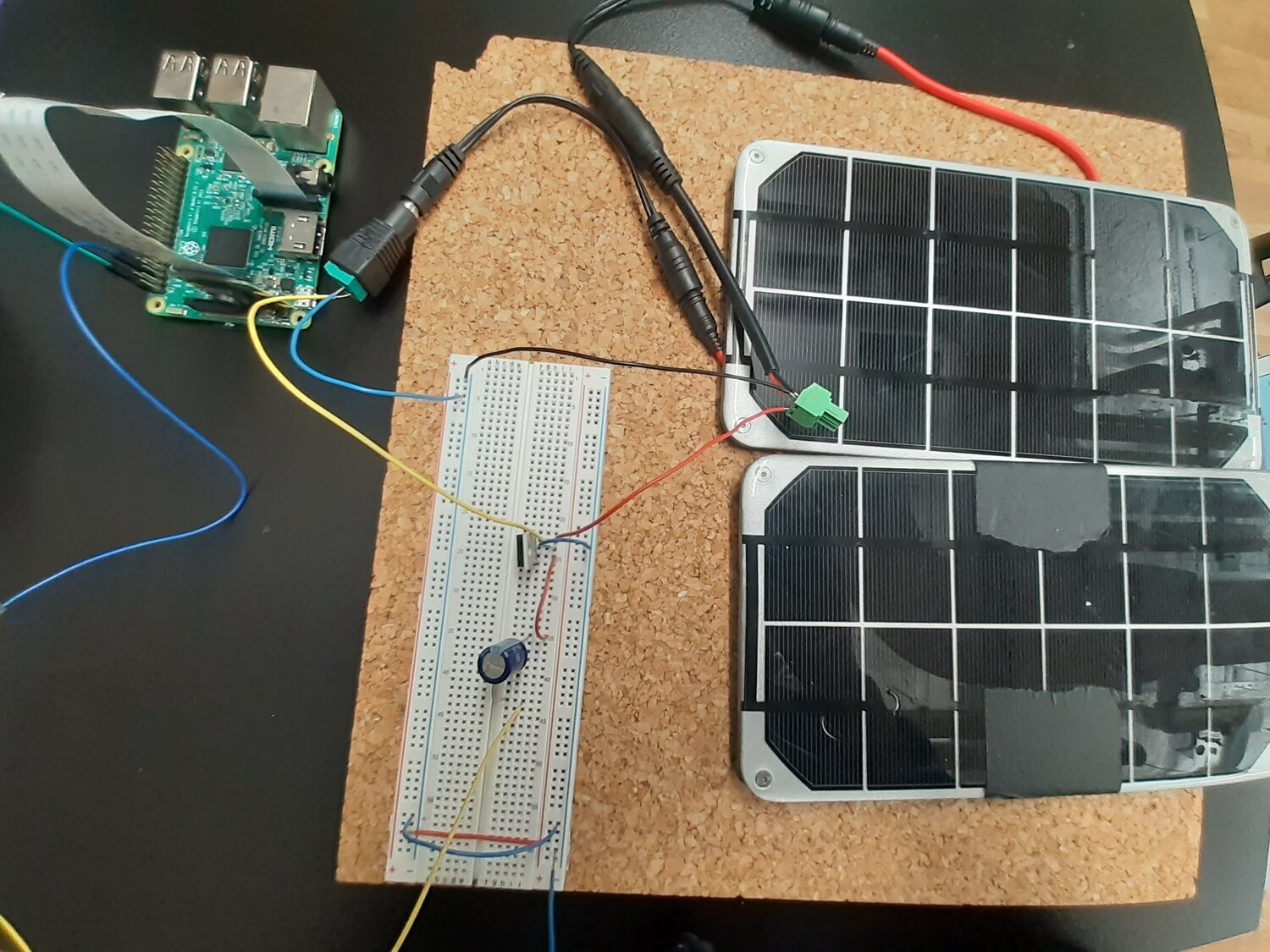
[5] Circuit iteration
CHALLENGES OF POWERING A PI
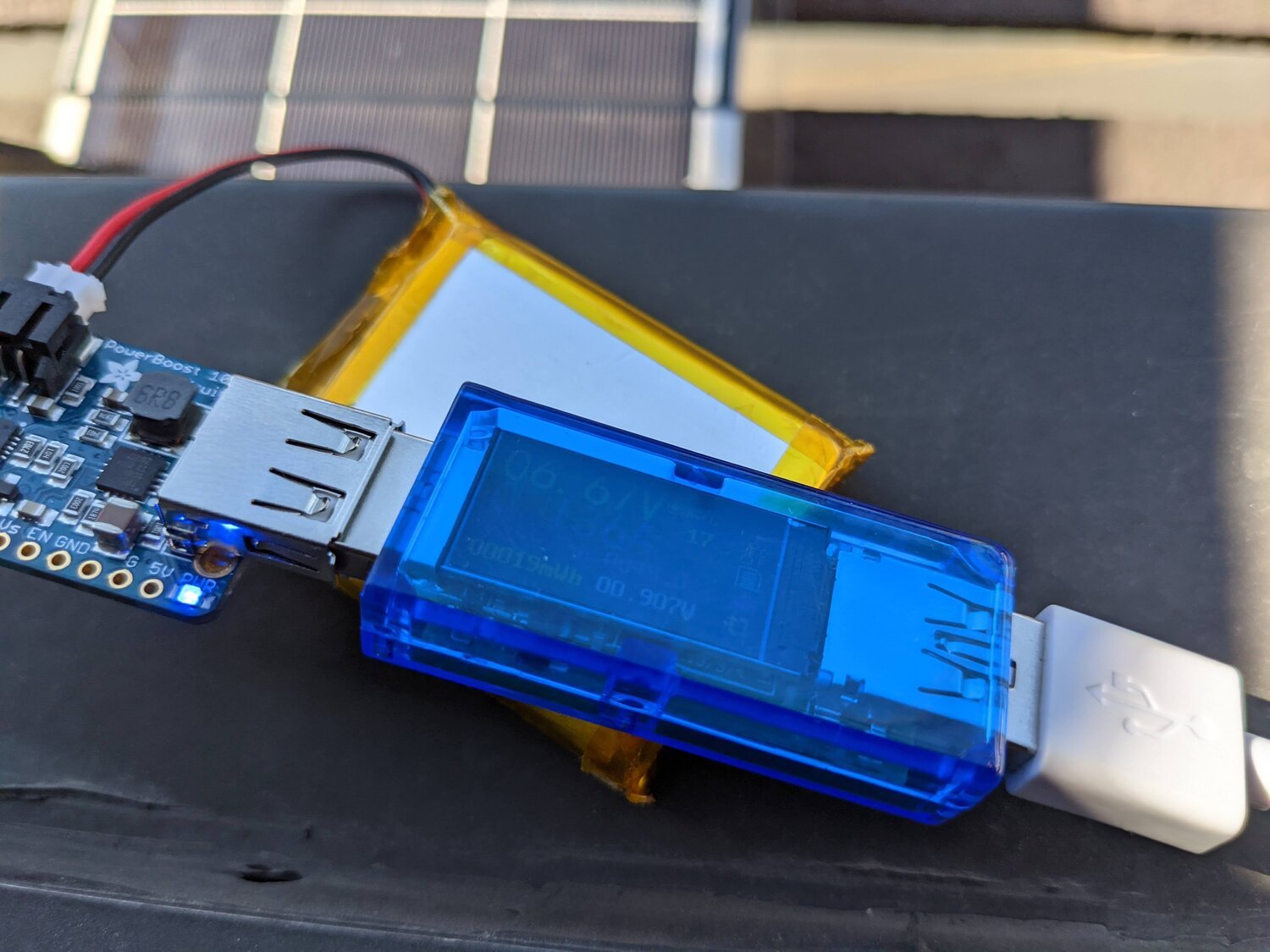
Powering a Pi for a small scale project is challenging for a couple of reasons. Unlike an Arduino or Pi zero, it needs an Amereage of 2.5A [4]. Small solar cells (6V, 2W) that I experimented with from the ITP floor didn’t give the required current. So I switched between 2-3 different solar cells before narrowing down to the 6W, 6V Adafruit cell.
PLANNING THE CIRCUIT
In the image on the left, you will notice two separate iterations using a slightly different circuit. [5] is the first one I tried using a 6V, 6W battery on Pi zero but I had to discard it since the Picam I used could only be plugged into a bigger board. In hindsight, I would have saved a lot of trouble if I bought peripherals for Zero. It would have made the setup sleek, low-powered and more robust. In [6], I worked with a smaller solar battery in series. I could switch the Pi ON but it was not enough to boot the Pi. [7] is the implemented circuit.
The Pi 3 uses 50mA - 536mA to boot and the [5] [6] circuit couldn’t supply enough current. So I made one last iteration. As shown in [7], I used a single mono-crystalline 6W, 6V cell that is connected to a power booster and supplies the current to the Pi. The image below also shows a circuit that includes a charge controller but during my implementation, I noticed that the boards were overheating due to battery discharge. I couldn’t pin-point any issues with the circuit so let go of it.
[6] Circuit iteration
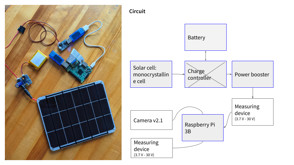
[7] Final implemented circuit
STEP 3
MEASURING THE DIFFERENT ACTIVITIES ON RASPBERRY PI
The Pi does three things: Boot, snaps a timelapse, and sends it to the database over Wifi.
Boot
#!/bin/bash
#take a timelapse every 4 seconds, over a period of 40 sec, 400 x 300, 80%quality, no preview

raspistill -t 40000 -tl 4000 -vf -w 400 -h 300 -o ./camera/image%04d.jpg -n

#upload to the server using curl
curl -F 'file=./camera/*.jpg' 'picspipe.herokuapp.com/upload'

#print a confirmation to a log file
curl | echo "picture uploaded at $(date)" >> ./logpipe/logfile.txt
Raspberry draws the max Amp during boot. Based on the readings, it started at ~50mA and the max it drew was 536mA before settling at 5.02V and 200 - 250 mA.
I added -n since that takes time to display and consumes energy plus the preview is unnecessary in my case.
2. Snaps a timelapse
I designed the Pi to take only 12 low-res images without a preview. So it’s extremely low energy consumption. Based on the reference on the left, shooting a high-quality video draws out ~480mA [8].
3. SEND IT TO THE DATABASE OVER WIFI
I don’t know how to measure this activity. It happens over a very short period.
So I did a small experiment where I tried to take timelapse over an hour and they keep the Pi idle for another hour to see the cumulative Amp and Volts. The video is documented below.
[8] Raspberry Pi cam power usage
Raspberry Pi console
Indoor testing
Outdoor testing
I set up the logger on the fire escape of my apartment. Below you will find some of the readings including the difference in current and voltage.